Address

10 Street Name, City Name

Country, Zip Code

Get in touch

970-461-1348

inside.sales@mdsusa.net

Follow us
Motor Diagnostic Systems Logo Home Page

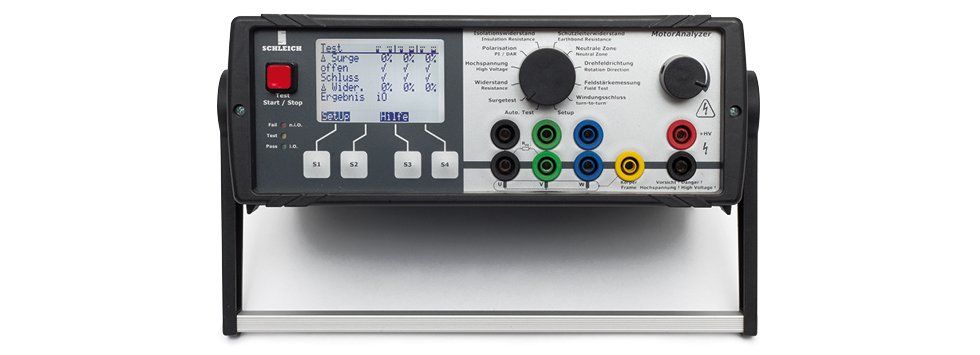
Schleich Motor Analyzer 1

MotorAnalyzer1 Universal tester for electric motors and windings 

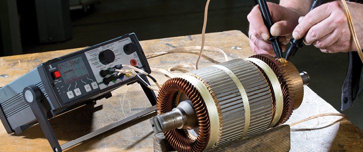
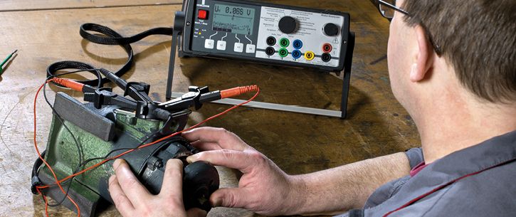
The MotorAnalyzer1 is a universal tester for testing electric motors

and windings. It combines 10 different test methods in a user-friendly

and mobile device. The combination of test methods, the compact

design and the battery operation make the MotorAnalyzer1 an ideal

tool for on-site use – even if the DUT is diffi cult to access.

MotorAnalyzer1 The entry-level device for your motor service

Compact design and a wide range of applications for troubleshooting in windings that are not live are the distinguishing features of this tester.  Ten reliable tests and test methods are built in. Due to its integrated rechargeable battery, tests can also be performed off-grid, without a power connection. It is a versatile tool for electrical engineering, motor repair, maintenance and servicing.


The versatile instrument.

Our MotorAnalyzer1 is a universal tester for electric motors and winding goods. It unites ten different test methods in one user-friendly and portable device. The combination of test methods, its ultra-compact design and the battery powered operation make the MotorAnalyzer1 the perfect tool for on-site use – particularly in difficult mounting locations.


To test an electric motor, the three winding leads and the motor housing are wired to the tester. The surge voltage and resistance tests are set in motion automatically. Subsequently, the motor is submitted to a high-voltage test in order to assess the quality of the motor in a fast and accurate manner.


MotorAnalyzer1 was designed for both in-house and on-site use. Off-grid battery mode lets you test electric motors (e.g. on a crane) accurately even in complex mounting locations. With MotorAnalyzer1 the user will have the ability to make a definitive GO/NOGO-assessment using all built-in test methods and advanced software diagnostics with superior visual support on-screen.

10 test methods in 1 device

Universal stator-, armature-, motor- and transformer-tester

10 test methods

autotest

surge voltage

resistance

high voltage DC

polarization index

insulation resistance

PE/GB-resistance

“neutral zone”-adjustment for DC motors

rotary field on stator or motor

winding fault location with a test probe for stator and armature

rotating switch for quick test method selection

automatic switchover between the three motor connection cables

built-in test result log

data transfer to PC via RS-232 or USB interface

easy-to-read large-screen graphics display

off-grid battery operation with battery status indicator

lightweight

Windows®-software for importing test results and printing test reports

Technical specifications overview.

Power supply


  • built-in battery
  • external charger

Autotest


  • automatic stator-, motor- and winding testing
  • automated fault detection

Surge voltage


  • automatic and manual surge voltage tests
  • 1-, 2- and 3-phase
  • Visual representation of the surge wave
  • automated analysis

Resistance

  • 1-, 2- and 3-phase
  • Imbalance analysis
  • precision 4-wire measurement
  • Temperature compensation

Insulation resistance


  • 0 – 4.000 V
  • up to 100 GΩ
  • manually adjustable
  • auto-programmable
  • in accordance with VDE 0701

Polarization index


  • 0 – 4.000 V
  • PI-measurement
  • DAR-measurement
  • automated measurement cycle

High voltage DC


  • 0 – 4.000 V
  • manually adjustable
  • auto-programmable
  • Voltage measurement in stages

PE/GB-resistance


  • in accordance with VDE 0701

Neutral zone” in DC motors

  • visual indication of the deviation of the ideal brush adjustment via a bar graph
  • acoustic indication of the deviation of the ideal brush adjustment via acoustic signal

Rotary field


  • stator-rotary field measurement
  • motor-rotary field measurement

Winding fault location


  • winding fault location with a test probe
  • visual indication of the winding fault location via a bar graph
  • acoustic indication of the winding fault location via acoustic signal


⇒ Find more details PDF here

Share by: